Single cracks in contemporary paintings on canvas can be disfiguring due to cupping. In 1999, the authors published a study of fourteen different methods for local treatment of such cracks, applied to slack paintings (Hough and Michalski 1999). Model paintings were created to simulate contemporary paintings of oil paint on acrylic ground on cotton duck fabric. Nine cracks, each 15 cm (6 in.) long, were created in each of nine paintings. Profiles of the treated cracks were monitored over a period ranging from five minutes to seventy days. Only three of the treatments gave good results at seventy days. The results were consistent with the known viscoelastic properties of the materials used. A year later, three paintings were keyed out in order to study the taut condition, where cupping is driven by stress alignment rather than curl, and to study the tendency of the repairs to surface. In 2018–19, the samples were reexamined. Surfacing had become pronounced in many but not all of the samples that had been keyed out: one treatment still looked good. In this paper, the mechanisms causing cupping and surfacing are modeled and the predictions compared to the experimental results.
40. Local Treatments of Cupped Cracks in Contemporary Paintings and Their Appearance after Twenty-One Years
- Mary Piper Hough, Head of Paintings Conservation, Library and Archives Canada, Ottawa
- Stefan W. Michalski, Heritage Conservation Scientist (retired), Canadian Conservation Institute, Ottawa
Introduction
Single cracks or localized cracks in contemporary paintings on canvas can be disfiguring due to cupping. A local treatment, if successful, has the advantage of avoiding risks that a whole painting treatment presents to the remainder of the painting. Although cupping may be removed temporarily by moisture, solvent vapors, and/or heat, maintaining flatness may require reinforcements, which in turn may surface.1 In 1999, we published a study of fourteen different methods for local treatments of such cracks in slack paintings (Hough, Mary Piper, and Stefan Michalski. 1999. “Preliminary Results of a Research Project Exploring Local Treatments of Cupped Cracks in Contemporary Paintings.” In Paintings I: Conservation and Restoration of Paintings, 303–11. Lyon: ICOM Committee for Conservation.). Here, we will discuss the appearance of these treatments in paintings twenty-one years later, with and without keying out (i.e., with both taut and slack conditions).
Mechanical Modeling
Curl and Stress Alignment
During curing, paint layers (which are “fatter” layers) attempt to shrink more than ground layers (which are “lean”). If a crack forms and if the painting is slack, this differential shrinkage curls the painting at the crack, as shown in figure 40.1a.
By combining equations from geometry with Timoshenko’s equation for curvature of a two-layer laminate (Timoshenko, S. 1925. “Analysis of Bi-Metal Thermostats.” Journal of the Optical Society of America 11: 233–55.), we can derive the height of the curl in the paint-ground laminate.2 Height depends on the difference in shrinkages, the thickness of the laminate (in this case, paint and ground), and the width (w) of the region that is free to curl. The inset graph in figure 40.1 shows cupping height (y-axis) for various laminate thicknesses (x-axis), for paintings where the paint layers are equal to, or not more than a few times thicker than, the ground, and are not especially soft compared to the ground.3 Plots are shown for a range of differential shrinkages, with 0.2% as a difference we can expect for an oil paint on a lean ground, whether oil or acrylic.4 The blue circle marks the predicted curl for the model paintings in this study. Much larger shrinkages due to severe aging or solvent leaching will drive much larger curl.
The size layer is not considered in this model for curl (equations for a three-layer system are beyond the scope of this paper). However, one can expect shrinkage of the size layer to counteract shrinkage of the paint layer, especially at low humidities, but in Hough’s measurements of curl in the experimental samples (see “Profile Measurement” below), curl definitely increased with lower RH (Hough, Mary Piper. 2000. “Local Treatments to Control Cupping Growth in Cracks: Experiments on Model Contemporary Paintings.” MAC thesis, Queen’s University, Kingston, Canada.),5 showing that shrinkage of the paint layer dominated shrinkage of the size layer. We can qualify this simple two-layer model for curl, paint-ground, as an estimate of the maximum expected curl.
Where the painting is cracked, the canvas acts as a hinge (fig. 40.1b). Curl is then limited by the surrounding area of the painting plus any overall tension. If the painting is keyed out, the canvas hinge and the cupping are pulled toward flatness, but this flattening reaches a limit when the canvas hinge aligns with the center of the tension located in the size, ground, and paint layers of the uncracked regions.6 Cupping cannot be flattened beyond this limit no matter how much tension is applied. This flattening limit halign is equal to at least half the combined thickness of canvas, size, and ground (for low-stiffness paint) and at most half the combined thickness of canvas, size, ground, and paint (for high-stiffness paints). In figure 40.1b, the simplest situation has been assumed, where the red line is in the middle of the size-ground-paint laminate.
Surfacing Mechanisms
If a reinforcement is added to the verso and if the painting has zero tension, then the result shown in figure 40.2a is plausible. In a painting with some tension (driven by keying out, gravity, or low humidity), the reinforcement will surface with a profile somewhere between the two extremes: a ridge if the reinforcement behaves like a chain (fig. 40.2b), or a plateau if the reinforcement behaves like a plate (fig. 40.2c). Additional distortions may be superimposed if there is differential swelling or shrinkage driven by heat, plasticizer, solvents, moisture, or an adhesive.
The deformations shown in figures 40.1 and 40.2 are not static; they can only be measured and understood within the framework of viscoelastic mechanics; that is, one must consider time. Large elastic deformations of paints can be accomplished in as little as seconds when high temperature and plasticizer are used, whereas at room temperature, large elastic movements take months or years. On the one hand, trying to bend a paint film quickly at room temperature will fracture it; on the other hand, successfully flattened paint can recover the memory of its old deformation over the course of months and years. (For a theoretical background, see papers in these proceedings by Hagan and by Daly-Hartin, Michalski, and Hagan.)
To maintain flatness over the years, a reinforcement must stress relax much more slowly than the paint layers. This suggests that one should select either inorganic materials (metal, glass) or highly cross-linked, filled polymers.
Butt Joints
Theoretically, the ideal solution to cupping at a crack would be to repair the crack itself—to make a butt joint. It is, unfortunately, extremely difficult in practice to make a butt joint that is continuous, reliable, and invisible.
Experiments
The aims of the study were as follows:
-
Make cracked model paintings that exhibit significant cupping
-
Subject the cracks to local treatments, orthodox and novel, that attempt to flatten cupping and restrain its reappearance
-
Document the cupping heights of the cracks as a function of time
-
Determine which treatments, if any, are visually acceptable
-
Apply the models of viscoelastic mechanics to the interpretation of the results
Preparation of Model Paintings
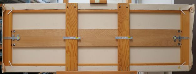
The model paintings follow a technique often used by artists from 1950s onward: oil paint on acrylic ground on cotton duck fabric. One or more localized disfiguring cracks have often been observed in such paintings. Nine paintings were prepared on commercial stretchers, 61 × 168 cm (24 × 66 in.), in landscape orientation. Two wide, vertical crossbars were rigidly attached to the top and bottom stretcher bars, so that tension could be released in the horizontal axis without disturbing the vertical axis. The corners of the stretcher were expanded 6 mm in each direction prior to application of the canvas, to permit slackening when needed.
After stretching the cotton duck, the perimeter was masked to create a 7.6 cm (3 in.) border of uncoated fabric. This flexible border reduced tension in the painted area, simulating the large slack paintings that were the focus of the study. The cotton was coated with three layers of acrylic ground, followed by six layers of lead white/zinc white oil paint. The total thickness of the ground roughly equaled the thickness of the paint. All layers were monitored by weight to ensure uniform application.
Cracking and Heat Aging of Model Paintings
To create multiple uniform cracks, a guillotine-like apparatus was made. The apparatus and painting were kept in a cold room at −5ºC (±2ºC) to ensure brittle, glassy behavior during impact. The painting was placed facedown over a narrow trench, and the dull blade was dropped. The amount of indentation was limited by an adjustable stop to avoid plastic deformation. Nine 15 cm (6 in.) cracks were created in each painting, parallel to the short dimension and spaced evenly along the long dimension. Fairly consistent, clean fractures with very little distortion of the canvas were obtained.
The paintings were keyed in to slacken them in the direction perpendicular to the cracks to facilitate curl. They were then heat aged for nineteen days at 41°C to speed any curing and relaxation processes prior to treatment (fig. 40.3).
Experimental Treatments
Of the fourteen local treatments tested, one included moisture and heat alone with no reinforcement; others included various sizing or adhesive methods, and eight were variations on the application of thin reinforcing strips adhered across the crack verso. Two implausible treatments using rigid plates applied to the crack verso were tested to establish baseline “flatness” data. Some treatments were derived from those in use at the time in the local treatment of cupped cracks or of tears; others were experimental designs. Variation in the resulting degree of stiffness was a main reason for choosing a treatment to see its ability to hold the cupping flat. Important also were the application from the verso, especially for paintings with sensitive surfaces, and the ease of removability of the added reinforcement. The treatments varied in the location of the added element, the adhesive, the reinforcement, or both, some of which have consequences for surfacing.
During treatment, the painting was placed facedown, and each crack was held flat for about thirty hours using a purpose-built suction table. For most treatments (2–11), the reinforcement was applied to the crack verso while the crack was held flat under suction. Eight simple suction tables were made to allow multiple treatments to be performed in one day, since pressure needed to be maintained for drying or curing.
All the strips of material used in treatments 4–11 were fabricated so that their thickness was the same (0.50 mm ± 0.05 mm). This thickness was fixed by the stainless-steel strips of treatment 4 (0.48 mm). Width varied between 0.64 mm (stainless-steel strips) and 2 mm. Various casting and molding techniques were employed, and a micrometer was used to check thicknesses. Strips 8 and 9 (wet treatments) were molded in situ, with steel strips present as thickness gauges. All strip treatments were applied across the crack verso and were spaced at 3.2 mm (1/8 in.) intervals, with alternating lengths of 25.4 mm and 12.7 mm (1 in., 1/2 in.), except treatment 8. Verso images of some treatments are shown in figure 40.4.
Details of each treatment are as follows:
-
Moisture, heat, and flattening; no reinforcement. Moisture was applied to the crack area at recto using damp, felted Gore-Tex for twenty-four hours, followed by suction from recto and heat from verso.
-
Acrylic plate, 3.2 mm thick, applied to the canvas over a wide area with five-minute epoxy. This was a benchmark reinforcement for experimental purposes, not a suggested treatment for paintings.
-
Epoxy/aluminum foil plate, 50 mm wide, attached with two layers of Beva 371 film.7 This was an exploratory treatment designed to test the behavior of very thin aluminum composites and continuous patches.
-
Individual stainless-steel strips (0.48 mm × 0.64 mm orthodontic “wire” with rectangular cross-section); attached with two layers of Beva 371 film.
-
Strips made of Epoweld 3672 epoxy filled with full-length glass filaments (50 µm diameter), oven-heated to improve curing of the epoxy; attached with two layers of Beva 371 film.
-
Strips made of polyester threads coated with epoxy (Epoweld 3672), oven-heated; attached with two layers of Beva 371 film.
-
Strips made of polyester threads coated with epoxy (Epoweld 3672), allowed to cure at room temperature; attached with two layers of Beva 371 film.
-
Strips made of polyester threads coated with epoxy (Epoweld 3672), applied wet to the crack verso. Four variations on thread length and spacing were tried.
-
Strips made of polyester thread coated with PVA ( Jade 403), applied wet.
-
Beva 371 size (1:1 naphtha) applied to verso of the crack area, 12.7 mm on each side of the crack, and dried for two days. A hot aluminum plate was applied, and the area was left to cool. Strips from treatment 6 were attached with two layers of Beva 371 film.
-
Acryloid B-72 size (20% in xylene) applied to verso of crack area, 12.7 mm on each side of the crack, and dried for two days. A hot aluminum plate was applied, and the area was left to cool. Strips from treatment 6 were attached with two layers of Beva 371 film.
-
Beva 371 size (1:1 naphtha) applied to verso of crack area, 12.7 mm on each side of the crack, and dried for two days. A hot aluminum plate was applied, and the area was left to cool. No reinforcement.
-
Acryloid B-72 size (20% in xylene) applied to verso of crack area, 12.7 mm on each side of the crack, and dried for two days. A hot aluminum plate was applied, and the area was left to cool. No reinforcement.
-
Epoxy (EPO-TEK 301) flowed into the crack from the recto to adhere the two fracture faces in a butt joint. Unlike in treatments 1–13, suction was applied from the verso by a Mitka suction table with the painting faceup. Then a hard, flat weight was applied over the crack area for twenty-four hours.
Profile Measurement
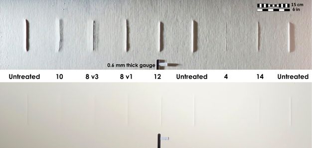
In the first phase of the study, the profiles of each crack were scanned using a mechanical scanner developed for this project. The scanner provided a profile of a 20.5 cm (8 in.) line perpendicular to the center of the crack, with a sensitivity of about 1µm in height. Unfortunately, over the years the scanner had been discarded, so for the height measurements at twenty-one years, we used calibrated raking-light photographs. Calibration was made using a 0.6 mm leaf from a feeler gauge, held firmly below each crack by magnets behind the painting.
For further information on the experimental methods and materials, and initial results for the slack painting condition, please refer to our article (Hough, Mary Piper, and Stefan Michalski. 1999. “Preliminary Results of a Research Project Exploring Local Treatments of Cupped Cracks in Contemporary Paintings.” In Paintings I: Conservation and Restoration of Paintings, 303–11. Lyon: ICOM Committee for Conservation.) or Hough’s thesis (Hough, Mary Piper. 2000. “Local Treatments to Control Cupping Growth in Cracks: Experiments on Model Contemporary Paintings.” MAC thesis, Queen’s University, Kingston, Canada.).
Taut Painting Condition
A year after the first stage of the project ended, three paintings that contained at least one of almost all the treatments were keyed out in order to study the taut condition where cupping is driven by stress alignment rather than curl, and to study the tendency of the repairs to surface. To ensure reproducible movement, a central crossbar was added to the long dimension, with adjustable turnbuckles that controlled tension perpendicular to the cracks (fig. 40.5). The arrangement of the nine cracks in a row ensured that even if carefully calibrated keying out did not yield exactly the same tension across all paintings, at least within each painting, samples would be subject to equal tension and could be compared directly and reliably.
Results
Results for each treatment are summarized in table 40.1 and presented visually in figures 40.6 and 40.7. Cupping heights over time for all treatments are plotted in figure 40.8. Here, only the highlights are noted, with further detail provided in the Discussion section.
| Treatment | Results: Visual appearance of crack in raking light (time after treatment) | |||||||
|---|---|---|---|---|---|---|---|---|
| No. | Size | Reinforcement | Adhesive |
Painting slack (70 days) |
Painting slack (21 years) |
Painting taut (21 years) |
Images (21 years) |
|
| Moisture and heat | 1 | Moisture, heat + flattening alone. No size, no reinforcement, no adhesive | Initially 1/2 height; in a few days, approached before-treatment height with more gradual slope; at 2 months, original steeper slope reappeared: crack profile narrowed + aperture opened | Crack has the appearance of an untreated crack | Crack has the appearance of an untreated crack; cupping height lower than in slack painting | Fig. 40.7 | ||
| Plates, for reference | 2 | — | Acrylic, 3.2 mm | Epoxy | Crack appeared flat; plate perimeter surfaced | Same as 70 days after treatment | NA—not keyed out | Fig. 40.7 |
| 3 | — | Epoxy/aluminum foil, 0.3 mm | Beva 371 film | Crack appeared flat; plate perimeter surfaced | Crack has slightly raised; surfacing still present | NA—not keyed out | Fig. 40.7 | |
| Strips | 4 | — | Stainless-steel strips | Beva 371 film | Crack slightly raised | Crack raised slightly higher; no surfacing | Same as for slack painting | Figs. 40.4, 40.6, 40.7 |
| 5 | — | Epoxy/glass filaments; heat cured | Beva 371 film | Crack slightly raised | Crack still appears slightly raised; no surfacing | Crack remains slightly raised; however, now with surfacing due to bending of strips; gradual slope | Figs. 40.4, 40.7 | |
| 6 | — | Epoxy/polyester threads; heat cured | Beva 371 film | Crack slightly to moderately raised; epoxy heat curing appears significant in stiffening compared to treatment 7 | Crack is moderately raised; no surfacing | Crack appears moderately to fully raised; surfacing is present | Fig. 40.7 | |
| 7 | — | Epoxy/polyester threads; room cured | Beva 371 film | Crack moderately raised | Crack is moderately raised, height higher; no surfacing | NA—not keyed out | Fig. 40.4 | |
| 8 | — | Epoxy/polyester threads; room cured | Threads applied wet | Crack slightly raised; epoxy flowed intermittently into crack for greater height control, resulting in stitched appearance | Crack moderately to fully raised; stitched appearance; no surfacing | Cupping height is lower than in slack painting; stitched appearance; surfacing is present | Figs. 40.6, 40.7 | |
| 9 | — | Jade 403/polyester threads | Threads applied wet | Initially 1/2 height; in a few days, approached before-treatment height with gradual slope; at 70 days, original steeper slope reappeared | Crack has appearance of an untreated crack; no surfacing | NA—not keyed out | Fig. 40.7 | |
| Size + strips | 10 | Beva 371, heat | Epoxy/polyester threads; heat cured | Beva 371 film | Crack was slightly raised; slight moating in sized area | Crack is slightly to moderately raised; strong moating, no surfacing | Crack approaches appearance of untreated; keying out removed appearance of moating; surfacing present | Figs. 40.6, 40.7 |
| 11 | B-72, heat | Epoxy/polyester threads; heat cured | Beva 371 film | Crack appeared moderately raised; strong moating in sized area | Crack is slightly to moderately raised; severe moating, no surfacing | Crack approaches appearance of untreated; slight moating is visible; surfacing present | Fig. 40.7 | |
| Size alone | 12 | Beva 371, heat | — | — | Crack appeared slightly to moderately raised; sized area was moderately moated | Crack has appearance of untreated; slight moating is visible: no surfacing | Cupping height is lower than in slack painting; moating not apparent; no surfacing | Fig. 40.7 |
| 13 | B-72, heat | — | — | Crack appeared to be half of before-treatment height; sized area was severely moated | Crack has appearance of untreated; strong moating is visible; no surfacing | Cupping height is lower than in slack painting; moating is minimized; no surfacing | Fig. 40.7 | |
| Butt joint | 14 | — | — | Epoxy butt joint | Crack appeared moderately raised | Crack appears moderately raised; no surfacing | Crack appears moderately raised; no surfacing | Figs. 40.6, 40.7 |
During the early monitoring of the cracked model paintings, prior to any treatment, cupping increased after the tension was released, exceeding the painting’s half thickness, thus confirming curl as the dominant driving force (Hough, Mary Piper, and Stefan Michalski. 1999. “Preliminary Results of a Research Project Exploring Local Treatments of Cupped Cracks in Contemporary Paintings.” In Paintings I: Conservation and Restoration of Paintings, 303–11. Lyon: ICOM Committee for Conservation.).
After the first seventy days, before any keying out, only three of the treatments (4, 5, 6) were successful in terms of visual appearance—rigid enough to hold the cupping down and insubstantial enough not to create new distortions.
After twenty-one years of being slack, only 4 and 5 remained visually acceptable, and no surfacing was present (see fig. 40.7, top row).
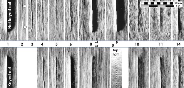
After twenty years of being taut (keyed out), many treatments showed pronounced ridge surfacing (see fig. 40.7, bottom row). Only 4 was successful: it held the cupping almost flat but did not provoke plateau surfacing. One of the treatment 4 samples is shown in figure 40.6, alongside other treatments as well as untreated cracks within a single painting.
For treatment 8, the epoxy was allowed to set up for a period before the suction was turned on. Despite this time allowance, the suction pulled the epoxy into the crack face, partially closing the crack and holding it flat intermittently—resulting in a partial (inadvertent) butt joint. This is visible when raking light comes from above, as in figure 40.7, bottom row: the crack has a stitched appearance and a comb-like shadow.
The cupping in the untreated cracks reached heights of ~0.7 mm in the slack paintings. In the keyed-out paintings, the cupping reached only ~0.51 mm, less than in the slack paintings, as expected (see fig. 40.1). On the verso, the canvas has followed the curling paint layers. No delamination was noticed in any of the samples.
Discussion
Final States of Treatments after Twenty-One Years
In terms of the predictions of curl (see fig. 40.1a), given the ~0.38 mm thickness of paint and ground for the model painting, assuming a region for unrestrained curl about 20 mm wide on each side of the cracks, and assuming the shrinkage differential between oil paint and acrylic ground of 0.2% estimated earlier, the result places the blue circle in the inset graph in figure 40.1, predicting a cupping height of ~1.6 mm. The average cupping height of untreated cracks in slack paintings, 0.68 mm, is less than half of this estimate, implying either that the estimate of shrinkage is too high or, more likely, that the canvas hinge (and perhaps the size) is restraining curl.
In terms of the predictions of stress alignment without reinforcements (see fig. 40.1b), given the thickness of the paint and ground, ~0.38 mm, and the canvas thickness of ~0.76 mm, then by the equation in figure 40.1b, we expect untreated, heat/moisture-treated, or size-treated cracks to have cupping height of ~0.57 mm. Untreated cracks in taut paintings (three samples) reached 0.51 ± 0.02 mm. If we estimate that half the ground sank into the canvas weave, then the prediction falls to ~0.52 mm, as observed. The cupping of heat/moisture treatment (1) reached 0.45 mm, 12% lower than untreated cracks, while size treatments (12, 13) reached 0.35 mm, 31% lower.
Keying out created ridge-shaped surfacing in all treatments that used reinforcements, except treatment 4, the steel; that is, all polymer reinforcements and the glass bundles embedded in a polymer bent at the crack, thus creating a ridge, as shown in figure 40.2b. Keying out generated consistent ridging heights: worsening treatments that did well when slack (except treatment 4), and improving treatments that had maximum curl when slack.
Both the ridge surfacing caused by reinforcements under tension and the moating8 caused by size treatments were precisely aligned with their location on the back of the canvas. There was no complex extension of visible deformation beyond the boundaries of the verso treatment.
In terms of the predictions of surfacing of reinforcements (see figs. 40.2b, 40.2c), given the thickness of all reinforcements of 0.50 ± 0.05 mm and the paint, ground, and canvas thicknesses specified earlier, we expect the height of surfacing to be ~1.2 mm (only ridge surfacing was observed). Heights for reinforced treatments using polymers (6, 8) ranged between 0.35 mm and 0.30 mm, respectively (see fig. 40.8, graph on right, top). The glass fiber reinforcement (5), while successful in a slack painting, surfaced as much as the polymer reinforcements when taut: 0.35 mm. None of the ridge surfacing of reinforcements reached the prediction of stress alignment; all remained at or below 0.45 mm, about a third of our prediction. This suggests that the treatments, although visually unacceptable, had functioned to some extent as intended. From another perspective, it is suggested that the tension applied by the keying out was not severe enough to achieve maximum surfacing.
Only one mystery remained: since the stainless-steel strips, treatment 4, did not bend at the crack, why did they not surface as a plateau instead? The simplest answer is that the amount of tension we provided by keying out was not enough to bend the paint and ground into the S shape required at each edge of the surfacing plateau of figure 40.2c. This is consistent with the conclusion that the tension in the keyed-out paintings, while enough to drive some ridge surfacing of polymer reinforcements, was not enough to drive the maximum predicted. In other words, the keyed-out paintings were tight enough to cause ridge surfacing of flexible reinforcements, but not sufficient to cause noticeable plateau surfacing. Unfortunately, the raking-light measurement method did not show small, gradual profile changes that more sensitive scanning might have detected. Perhaps our expectations of plateau surfacing were biased by observation of old patches that employed generous amounts of glue. These generate huge forces during low humidity, independently of keying out, and are much thicker than the reinforcements we used.
Viscoelastic Response over Time
In the graph on left in figure 40.8, we can follow the viscoelastic behavior of the treatments that were never keyed out, starting at five minutes after they were released from the suction table up to twenty-one years later. This type of graph—the logarithm of an elastic measurement versus the logarithm of time (a log-log plot)—is conventional in viscoelastic studies of polymers, because it can be placed in the context of master curves, as described elsewhere in these proceedings by Daly Hartin et al. and by Hagan. The heavy gray line at the top of the graph on left in figure 40.8 shows the slope of the master curve for stress relaxation of oil paintings measured by Daly Hartin et al. for the range of five minutes to one hundred years, which was 1/13, that is, 1 log unit in height for each 13 log units of time.9 The overall slope of the treatments that failed (and allowed the cupping to return) is similar to this slope. Even sized samples with a rapid increase in cupping in the first few hours followed by a striking decrease that lasted several months (treatments 10, 11, 12, 13), did return over the years to an overall slope of ~1/13, if one simply considers the first and last data points.
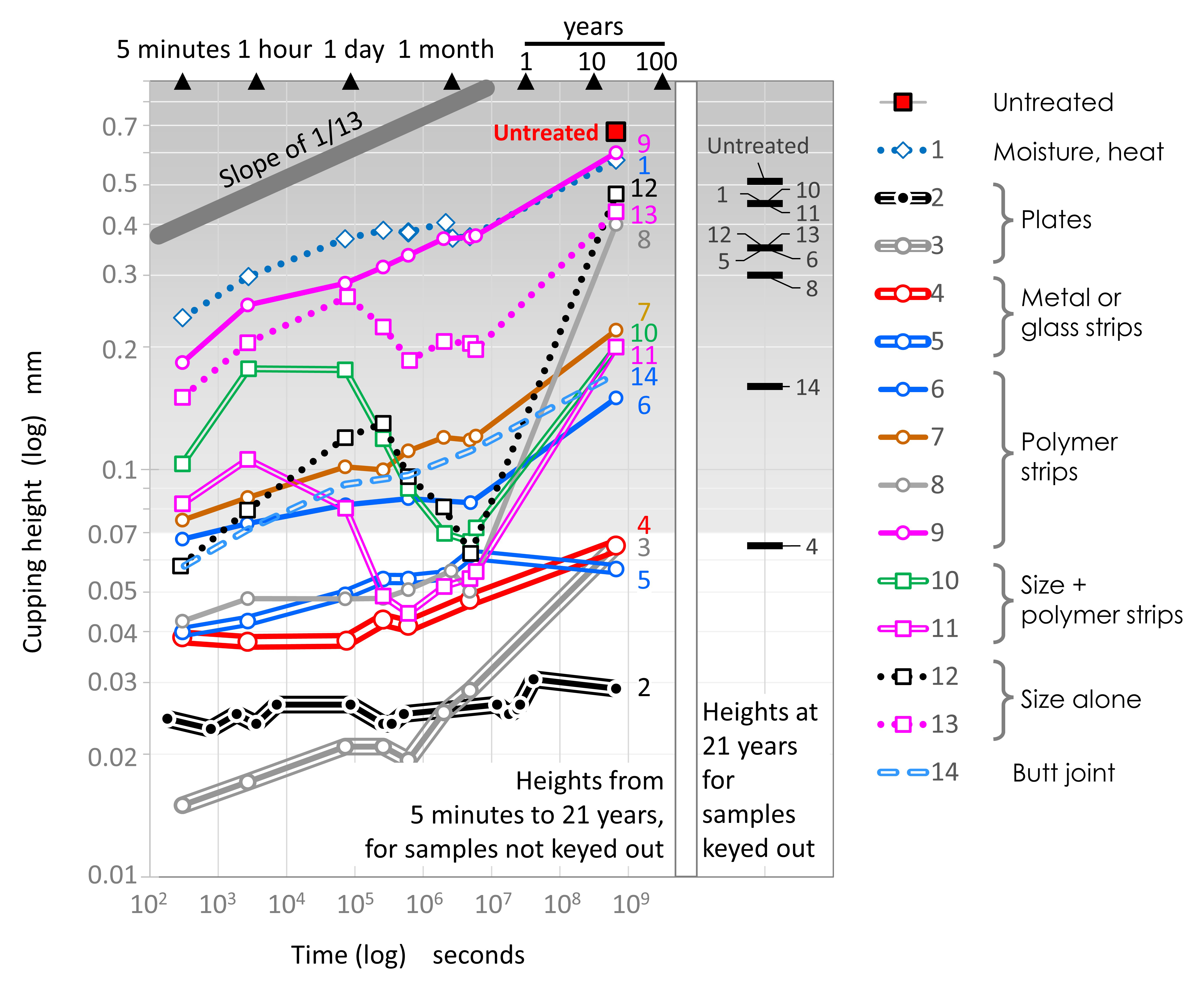
Treatment 1 (heat and moisture) also shows a small wobble in its plot, though not as pronounced as that of the sizes. This plateau between a few days and a few months led us to believe in our 1999 paper that this was a final plateau, but over the last twenty-one years it has returned to its initial rate of climb and reaches just short of completely untreated cracks.
The spread in the five-minute data points shows the diminishing springback of cupping immediately10 after the suction pressure was released. As expected, heat and moisture without reinforcement (treatment 1) has the largest springback, about one-third of the twenty-one-year cupping; by the first month, the second third recovers. Treatment 9 behaves similarly—demonstrating that a non-cross-linked polymer with a low glass transition temperature, such as the PVA ( Jade 403), offers negligible resistance. The benefits, if any, of such treatments are transitory. Remaining five-minute data points are in the expected order of increasing stiffness and less springback: polymer, then glass, then metal.
Since glass fibers (treatment 5) do not relax, the epoxy matrix binding them must have relaxed by shearing between filaments.
The difference between treatments 6 and 7 shows the benefits of heat-curing the epoxy to decrease its relaxation.
The butt joint (treatment 14), although not perfect in adhesion, kept the cupping at around a quarter of untreated heights throughout the duration, while climbing at the master slope of ~1/13.
The benchmark plate treatment (2), which within experimental error can be considered a flat line, demonstrated that it is possible to hold the cupping completely flat with a thermoset adhesive that soaks into the canvas and is cemented to a thick, rigid plate. It also established that the suction table could hold the cupping flat to within 0.025 mm on all treatments prior to release of the suction. The thin aluminum foil treatment (3) did not appear to bend either, but it did allow small cupping to emerge over the twenty-one years, as did treatments 4 and 5. All three showed very slow climbs toward a similar, nondisturbing height at twenty-one years. These cuppings are extremely low and narrow, and although the canvas could easily be seen to follow the large deformations of unsuccessful treatments, it was not possible to determine if the back of the canvas had followed exactly these very small deformations. A cupping height of 0.06 mm is only 8% of the thickness of the canvas (0.76 mm), so a slight bulging of the canvas threads would be enough to allow this curl of paint, and even if Beva entered the threads, as a thermoplastic it could certainly flow over the decades, allowing the canvas to bulge.
Conclusions
Our conclusions fall into two categories: those that have practical ramifications and those that are more theoretical.
Practical Conclusions
-
The application of a local adhesive in solvent (naphtha or xylenes) as a size (treatments 10–13) results in distortions (moating) that do not completely disappear.
-
Surfacing of local reinforcements is driven by tension in the painting. Ridge surfacing of flexible reinforcements occurs at lower tension than plateau surfacing of rigid reinforcements (assuming paintings with similar structure to our model painting, or those with even thicker paints or grounds).
-
Keeping the first two conclusions in mind, good results are possible if the reinforcement, such as metal, does not stress relax; if it is thin, such as very thin stainless-steel strips (treatment 4); if it is spaced and feathered; and finally, if the painting is under only moderate tension.
-
The neatest theoretical solution to both cupping and surfacing would be to adhere the fracture faces in a butt joint. Treatment 14 showed moderately good control of cupping. This treatment may eventually fail, but at least it will never surface. For this reason alone, more study of this option is warranted.
-
Data on samples before treatment showed that low RH substantially increases curl (Hough, Mary Piper. 2000. “Local Treatments to Control Cupping Growth in Cracks: Experiments on Model Contemporary Paintings.” MAC thesis, Queen’s University, Kingston, Canada.). Low RH also drives overall tension in a painting. Therefore, low RH will drive curl in slack paintings and surfacing in taut paintings.
-
Careful lighting can reduce the visibility of cupping.
Theoretical Conclusions
-
The slow return of cupping over time is the result of viscoelastic phenomena that are consistent with the master curves for paintings presented by other authors in these proceedings.
-
In taut paintings, cupping of untreated cracks or treatments not using reinforcements was consistent with the model predictions for stress alignment.
-
In taut paintings, ridge surfacing of reinforced paintings was less than the maximum predicted, indicating that all reinforcements resisted bending to some degree at the level of tension used.
Notes
-
Surfacing refers to the development at the surface of a painting of a deformation that corresponds to the shape of a local repair applied to the verso of the painting, such as a patch. ↩︎
-
Timoshenko derived the curvature of any two-layer laminate with differential shrinkage. If the differential shrinkage is (ε1−ε2), m is the ratio of the two thicknesses, n is the ratio of the two moduli of elasticity, and t is the laminate thickness, then radius of curvature is R=(t*(3*(1+m)^2+(1+m*n)*(m^2+1/(m*n))))/(6*(ε1−ε2)*(1+m)^2). The height h of the arc over a base of w and curvature R is h=R-(R^2-w^2). See https://www.mathopenref.com/sagitta.html. ↩︎
-
Given initial values of m=n=1 (see note 2) a plot of h stays within 25% of initial value despite changes in thickness ratio, n, by a factor of 3, or changes in elasticity ratio, m, by a factor of 7. Heavy impasto, or paints known to be soft, such as poor driers, will need the full equation, rather than the inset graph in figure 40.1. ↩︎
-
Curing shrinkage of linseed oil was suggested as a contributor to paint failure as early as 1929 (Clark, G. L., and H. L. Tschentke. 1929. “Physico-Chemical Studies on the Mechanism of the Drying of Linseed Oil I—Changes in Density of Films.” Industrial and Engineering Chemistry 21, no. 7: 621–27. https://doi.org/10.1021/ie50235a003.). Pure medium with driers, cured in the dark, shrank 1%–1.6% by volume, so 0.3%–0.5% in length. A paint of 35% pigment volume concentration (PVC) would experience ~65% of pure oil values, so ~0.2–0.3%. A ground at critical PVC would shrink negligibly in comparison. Browne reported dimensional change for films of linseed oil paints after they were released from the casting substrate and exposed to cycles of high RH (Browne, F. L. 1955. “Swelling of Paint Films in Water, III: Absorption and Volumetric Swelling of Bound and Free Films from Air at Different Relative Humidities.” Forest Products Journal 5: 92–96.). Michalski plotted the nonrecoverable shrinkage from Browne’s data: ~0.3% for an oil paint of 30% PVC, consistent with Clark and Tschentke (Michalski, Stefan. 1991. “Paintings: Their Response to Temperature, Relative Humidity, Shock, and Vibration.” In Art in Transit: Studies in the Transport of Paintings, edited by Marion Mecklenburg, 223–48. Washington, DC: National Gallery of Art.). ↩︎
-
Since the RH in the room where cupping was measured varied gradually over the course of the study, all cupping heights prior to treatment were plotted versus RH in order to derive a correction factor to normalize results to 50% RH. The factor was 2.1% height increase per 1% RH drop, for example, 21% height increase when RH is reduced from 50% to 40% RH (slack paintings). ↩︎
-
The stress-alignment concept was introduced to our field in an unpublished report by Marion Mecklenburg. His original term was “force realignment” (Mecklenburg, Marion F. 1982. “Some Aspects of the Mechanical Behavior of Fabric Supported Paintings: Report to the Smithsonian Institution.” Unpublished report, Smithsonian Museum Conservation Institute, Washington, DC. Reprinted in Dawn V. Rogala, Paula T. DePriest, A. Elena Charola, and Robert J. Koestler, eds. The Mechanics of Art Materials and Its Future in Heritage Science, 107–29. Washington, DC: Smithsonian Contributions to Museum Conservation, 2019. https://doi.org/10.5479/si.11342126.). ↩︎
-
The original formulation of Beva was used in all experiments. ↩︎
-
Moating is the development of a depression resembling a moat in a treated area of the painting, in this case, a depression encircling the crack. ↩︎
-
The slope of the stress relaxation is actually negative 1/13, the mirror image of the +1/13 of creeping of cupping. ↩︎
-
There is no “immediate” time zero in viscoelasticity; the springback would have occurred during several milliseconds as the suction pressure decreased, and with the correct tools one could have measured cupping heights growing from those milliseconds forward to our first data point at five minutes. Milliseconds would enter the glassy plateau shown by Daly Hartin et al. for millisecond events. ↩︎