Chicago
Mille, Benoît. “Case Study 1. Reconsideration of a Monumental Roman Relief: Great Dolphins of Vienne, France.” In
Guidelines for the Technical Examination of Bronze
Sculpture, by David Bourgarit, Jane Bassett, Francesca G. Bewer, Arlen
Heginbotham, Andrew Lacey, and Peta Motture. Los Angeles: J.
Paul Getty Museum, 2025.
https://www.getty.edu/publications/bronze-guidelines/case-studies/1/.
MLA
Mille, Benoît. “Case Study 1. Reconsideration of a Monumental Roman Relief: Great Dolphins of Vienne, France.”
Guidelines for the Technical Examination of Bronze
Sculpture, by David Bourgarit et al., J. Paul Getty Museum, 2025,
https://www.getty.edu/publications/bronze-guidelines/case-studies/1/.
Accessed
DD Mon. YYYY.
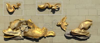
Fragments of a unique, large-scale,
gildedDefinition: gilding: The application of gold
to the surface of a bronze sculpture. This can be
achieved by a variety of methods. Traditionally
gilding was mainly undertaken using leaf gilding or
mercury gilding. Starting in the nineteenth century,
…More
Roman relief unearthed in the early nineteenth century
in Vienne, France, were the subject of an extensive
conservation campaign that included a multidisciplinary
technological investigation. The results not only shed
new light on the skillful methods of production that
went into the object, but also led to a reinterpretation
of the group’s composition and resulted in the
fragments’ rearrangement for display.
Context
The discovery of the dolphins in Vienne, France
(fig. 440)
In 1839, during excavations for a new quay on the
riverbanks of the Rhône in Vienne, engineers using a
pile driver unearthed what were described as a group of
“imposing metallic fragments.” These were a rare
discovery: the remains of a monumental gilded
bronzeDefinition: bronze: Depending on the user,
“bronze” may designate a copper alloy that has tin
as the primary added element or any other
copper-based alloy. We recommend using the term
“bronze” specifically for copper-tin alloys unless
qualified by another …More
relief representing swimming dolphins consisting of two
heads, a body in two fragments, and three tails. This
sculptural group, now known as the Great Dolphins of
Vienne, is a rare surviving example of such reliefs from
the Roman world.
Occasions for technical studies
(figs. 447, 448)
The bronze fragments had been studied in the 1960s.
Based on the surviving tails, the proposed
reconstruction of the relief’s original composition was
a five-meter-long frieze of three dolphins swimming in a
row. The visual examination already made clear that
joints were present, and that the relief surface was
extensively repaired. In 2006, the Vienne museum decided
to renovate the presentation of the dolphins. Given the
fragmentary nature and the complicated reading of the
find, the museum requested a thorough technological
probing as part of the conservation process, which
addressed a series of questions about the sculptural
group.
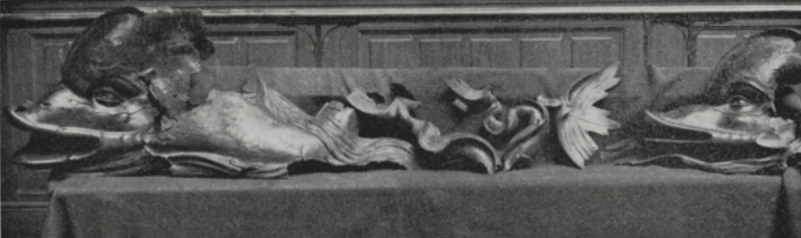
ExpandFigure 447The Museum of Vienne’s former presentation of the
Great Dolphins of Vienne, Roman period,
Vienne, France, 2nd century CE, max L. 260 cm (Musée
des Beaux-Arts et d’Archéologie de Vienne, France,
inv. R.1998.2.43). From Boucher 1964.
The main questions
(figs. 440, 441, 442, 443, 444, 445, 446)
How was it made?
How do the surviving fragments fit together?
Why was it so heavily repaired?
What may have been the original iconography and
composition of the full relief?
Visual examination
Some important new findings
(figs. 456, 459)
By puzzling through the physical evidence on the
fragments, the scientist-conservator team discovered a
previously undetected connection between the two dolphin
heads. Closer study of the fragments proved that the
dolphins were originally side by side, hitched together,
thereby fundamentally modifying our understanding of the
relief’s composition.
At the same time, they noticed a neatly cut-out area at
the top of the dolphin in the foreground: this is
possibly where a rider may have been posed.
It also became clear that the deformation and
fragmentation in one area of the relief was largely the
result of the violent and high-speed impacts of a 13 ×
13 cm implement—very probably the pile driver used in
1839.
Reconsidering the original composition
(fig. 459)
The new understanding of the arrangement resolves some
iconographic inconsistencies. The dolphin in the
foreground turns its head toward the viewer while the
one in the background is presented in profile,
reinforcing the perspective. In the same way, the wave
rising behind the head of the foremost dolphin and
descending over its body and tail should be read as
passing between the two dolphins. The cutout at the top
of the foreground dolphin could correspond to the inset
of a rider such as Eros. The existence of three dolphin
tail ends still raises questions. Were more than two
dolphins hitched together? The newly determined
perspective, the structure of the waves, and the
presence of the upper edge preserved in most places make
this an unlikely scenario. Instead, the tail could
belong to one of a second pair of dolphins, or—given how
widely it is splayed—to an unhitched, frolicking dolphin
diving into the waves.
How was the wax model made?
(figs. 84, 86, 450)
Examination of the rear surfaces of the fragments
revealed evidence that the sculptor worked in wax and
had access to what would have been formed as a wax shell
in a
moldDefinition: mold: A three-dimensional negative
form made of one or more parts that serves as a
matrix for the production of a positive by casting
or pressing malleable material into it. Molds allow
for the production of one or more copies of an
original …More—in other words, an indirect
lost-wax castingDefinition: lost-wax casting: A technique in
which a model made of wax is embedded in a
refractory mold that is heated, thereby melting out
the wax and creating a void to be filled with molten
metal. Two primary variations of the technique are
referred to as “direct” …More
process. One finds, for instance, a series of marks made
by dragging a tool through a malleable material that
were ultimately translated into bronze.
The presence of numerous
spruesDefinition: sprue: Any channel that feeds
metal to the mold, in contrast to a vent, which lets
air escape. Both sprues and vents make up the “sprue
system,” which circulates bronze from the pouring
cup through the refractory mold and allows air and
casting …More
on the reverse also proves that the wax
modelDefinition: model: The creation of a bronze
may involve a series of models and molds that can
differ in size and material depending on the
artist’s design process, and ultimately also on the
casting process chosen to create the bronze version.
The model is a …More
was worked from the back surface, and therefore not
built up directly on a
coreDefinition: core: The portion of the
refractory mold that defines the internal space in a
hollow bronze sculpture. It may be formed in a
variety of ways and is usually (but not always) made
of similar material as that used for the outer
portion of the mold. …More.
The wax heads were made of separate parts that were
joined in the wax. This can be seen in the lips, for
instance, which appear to have been made up of several
discrete sections. The wax joints would further confirm
the use of an indirect process. The overall even
thickness of the bronze walls, which was confirmed by
radiography (see “Summary of main technological features
observed at the back of the dolphins” below) points to
the probable use of a wax slab process, as that would
offer greater control than other processes such as slush
molding (see
I.3§1.3.4).
How were the segments of the relief assembled?
(figs. 460, 462, 463, 466, video 12)
Once all the separate parts were
castDefinition: cast (v.): In the sculptural
context, the verb refers to pouring a slurry or
liquefied material (e.g., plaster, wax, metal) into
a hollow matrix or mold that will determine the
shape of the material in order to produce a cast
(n.).More, the vast puzzle of primary castings had to be
assembled. To achieve this, the Roman
foundersDefinition: founder: Expert head of the
foundry or the person who pours the metal. Person(s)
responsible for the translation of the artist’s
sculptural model into cast metal sculptures. This
may entail a variety of specialized operations, from
mold making to …More
responsible for the relief used flow-fusion
weldingDefinition: welding: A technique for joining
separately cast parts using high temperatures
resulting in partial melting of the parts. A filler
metal is often applied.More, a technique learned from ancient Greece, where it had
been practiced since the fifth century BCE.
Recent scientific studies and characterizations of
ancient welds, with experimental simulations in the
laboratory, have shed more light on the long-forgotten
process (video 12;
I.5).
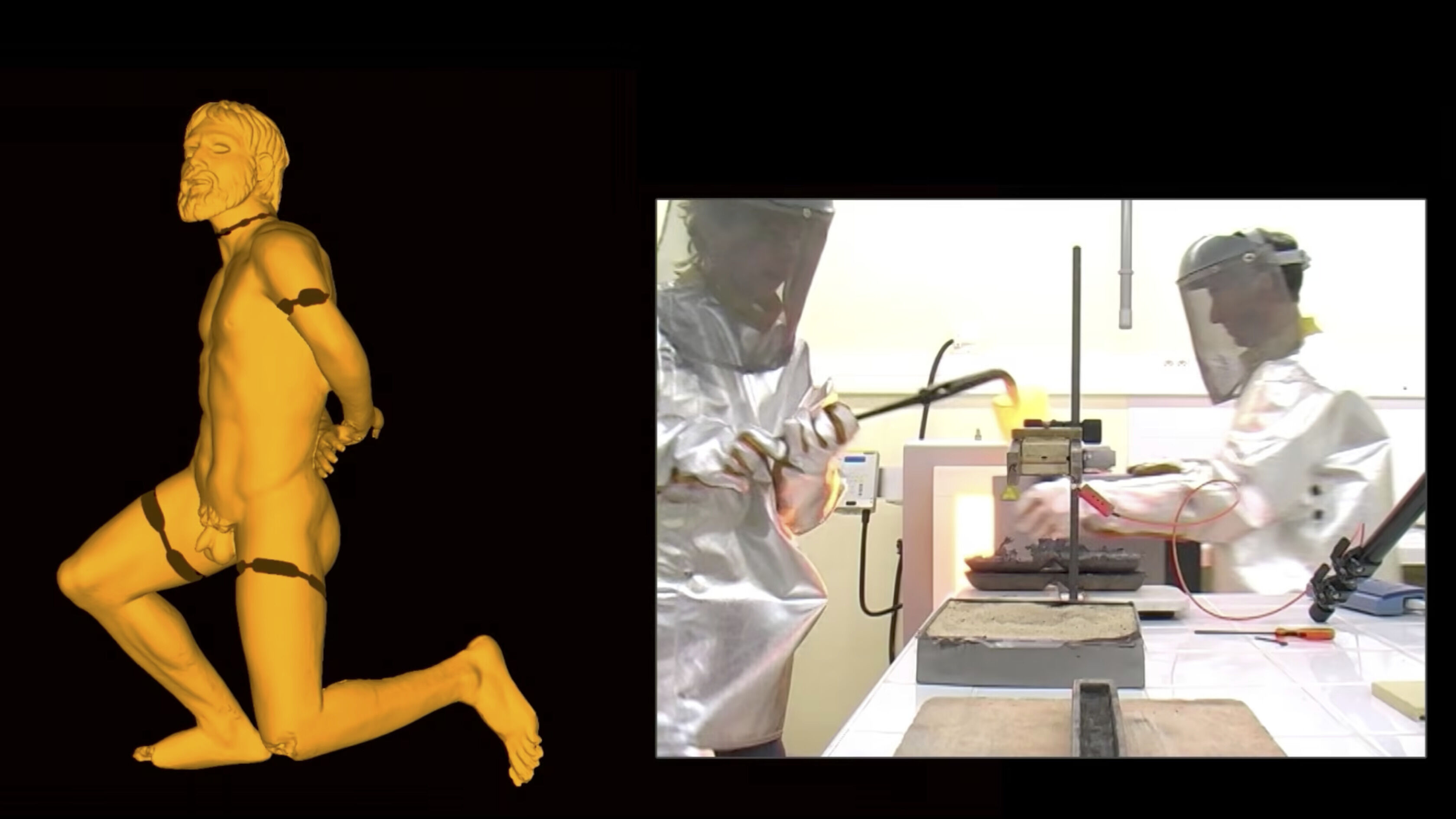
ExpandVideo 12Flow-fusion-welding laboratory experiment carried
out at the C2RMF, Paris, showing the fabrication
process for the Captive Gaul, Gaul, last
quarter of the 1st century BCE, H. 63 cm (Musée
départemental Arles Antique [MDAA], France, inv.
Rho.2007.06.1962), excerpted from a didactic video
presented at the exhibitions
Arles, les fouilles du Rhône, Musée du
Louvre (March 9–June 25, 2012), and
César, le Rhône pour mémoire, 20 ans de fouilles
archéologiques, Musée de l’Arles antique, France (November
2009–January 2011). See Azéma et al. 2013. For the
complete original video visit
https://youtu.be/vXPmorUKJuc.
With its three-plus linear meters of weld joints, the
Vienne dolphin relief bears testimony of the extensive
application of this complicated method of assembly. And
while the remains of the relief represent only a small
part of the original sculpture, they provide a window
into the exceptional scale and ambition of this work.
Some welds measure more than the staggering 70 cm long
one seen here. The fact that these joints were achieved
in a single
pourDefinition: pour: The operation of pouring or
casting metal into the refractory mold.More
bears witness to the great mastery of the founder. The
welds were very wide and the flow of metal must have
been contained, probably by channeling the welding metal
with a
refractory moldDefinition: refractory mold: A temporary,
heat-resistant, cohesive, porous mass that captures
the fine impression of the model to be reproduced
and forms the void into which the molten metal will
be cast. Investment, green sand, and ceramic shell
are examples of …More
that covered the whole weld path. Despite the
channeling, some leakage did occur (see also
fig. 467).
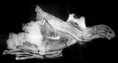
ExpandFigure 462Detail of an X-radiograph of a dolphin’s body in
which the denser welding zone appears as a brighter
white area in the center, the rivets show up as
small white donuts with darker centers, and porosity
appears as black flecks.
Great Dolphins of Vienne, Roman period,
Vienne, France, 2nd century CE, max L. 260 cm (Musée
des Beaux-Arts et d’Archéologie de Vienne, France,
inv. R.1998.2.43). For a description of all visible
technological evidence, refer to
figs. 367,
467.
Bulk alloy analyses by inductively coupled plasma with
atomic emission spectroscopy (ICP-AES, see
II.5§3.1) on drillings indicated a difference in the alloy used
for the different sections and welds. The alloy of all
of the primary castings is in the range of 3–4% tin, 5%
lead, and the welds are 1–2% tin, 5% lead.
Structure of the assemblage using X-radiography
(fig. 367)
X-radiography confirmed that the metal walls of the
separately cast sections are relatively thin and even
across the board (measured at 4–6 mm), including the
mouth area, even though it is in high relief. It also
helped to clearly map out the extent of the assemblage:
the welds show up as irregularly shaped, lighter swaths
that correspond to the thicker—and therefore
denser—metal joints.
The vast amount of repair work that the relief
necessitated, especially in the central area, is visible
as well. The edges of the many polygonal
patchesDefinition: patch: A type of repair most often
mechanically set into the bronze surface, but which
may also be soldered, welded, or cast into place
(see
I.4). Patches are most often made of cut-out pieces of
copper alloy that are the same as …More
that were inset into the outer surface to repair the
innumerable small flaws are recognizable, as are the
copper rivets, which will be further discussed below.
Proposing a casting plan
(fig. 367)
Roman founders did not have the technological know-how
to cast complex pieces such as the dolphin relief in a
single large pour, so they cast larger sculptures in
smaller sections (primary castings) and then joined the
metal parts by flow fusion welding (see
I.5§1.1). Careful examination of the fragments and the
corresponding radiographs, which helped locate the
joints, led to the proposal of a
casting planDefinition: casting plan: A methodological
tool that has been developed by researchers to
reverse engineer the casting sequence of a bronze
sculpture and visually represent the separately cast
parts. It is based on the evidence presented in the
object and attempts …More
for the eleven extant pieces of the large relief. It
provides some idea of how the original model was divided
up to facilitate casting.
How was the cast repaired?
(figs. 367, 464, 465)
All large ancient bronzes, even exceptional commissions,
will inevitably have some
casting defectsDefinition: casting defect: An unintended
imperfection on a bronze that occurs during casting
and appears as a more or less subtle discontinuity
in the desired form and is associated with either a
lack or an excess of metal. See
I.3.More, as is reflected by the large number of repairs. The
Vienne dolphins are no exception: if the extant portions
are anything to go by, the relief was heavily flawed.
Repairs cover 25 percent of the exterior surface. But
once they were covered by gilding, they would have been
nearly invisible.
Close examination of the surfaces, aided by cleaning
during conservation, showed that the external bronze
skin is riddled with endemic
porosityDefinition: porosity: A common type of casting
flaw that includes a group or area of cavities
caused by shrinkage or trapped gases. Porosity may
vary considerably in dimension and may or may not
break through the surface of the bronze. See …More
(fine holes that formed in the metal during casting) and
repairs. These are even more clearly visible in the
radiographs (see
fig. 367).
It was possible to tally no less than 265 patches made
of bronze. Many of the largest ones (a total of 178)
were fastened to the primary
castDefinition: cast (n.): A sculpture or more
generally an object that is shaped by pouring a
molten material or a slurry into a mold in which it
will solidify. Plaster of paris, metal, and wax are
among the cast-forming sculptural materials
routinely involved in …More
from the back with copper rivets.
Summary of main technological features observed at the
back of the dolphins
(fig. 467)
The diagram synthesizes the evidence preserved from the
various stages of production of the relief beginning
with the creation of the wax model. The discrete,
indirectly formed sections were joined in the wax (light
blue lines). Sprues and wall fasteners (blue) were
modeled in wax and joined to the back.
The separately cast bronze pieces (fine red lines
indicate the edges) still preserve some
core pinsDefinition: core pin: A metal rod, nail, or
wire that is embedded in both the core and the outer
mold and serves to secure the core in place during
the pour. Core pins have traditionally been made of
copper alloys, iron, or steel, and today are
generally made …More
(black dots) and
flashingDefinition: flashing: A ridge of excess metal
that can occur when molten metal enters cracks in
the refractory mold (both outer and core). Flashing
most often rises perpendicularly to the inner or
outer wall of bronze, although a gap in consecutive
layers of …More
(lilac).
The separate bronze pieces were joined by massive flow
fusion welds (red to pink).
And the many flaws were fixed with
cast-on repairsDefinition: cast-on repair: A type of repair
consisting of a localized cast of molten copper
alloy to fill cavities or other casting defects.
Cast-on repairs may fill a void in the sculpture or
secure a separately formed patch or element to the
cast.More
(brown) and innumerable patches (green), many of which
were reinforced with copper rivets (dark green).
Conservation treatment and surface polychromy
(figs. 290, 380, 381, 468)
As conservators prepared the careful mechanical cleaning
of the surface, examination of all of the fragments also
served to assess their structural and physico-chemical
condition and any alterations of the metal. Focus was on
the removal of the bronze
corrosionDefinition: corrosion: A chemical process that
causes a metal such as bronze to change from a
metallic state into a chemically more stable mineral
compound known as a corrosion product.More
products that masked the entire surface. It was decided
early on to clean the reverse as well in order to
enhance the readability of technical features and learn
as much as possible about the object’s manufacture.
There was no question of attempting to address
deformations or fill losses.
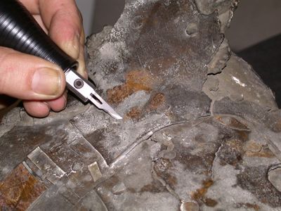
During the cleaning, which was mostly done mechanically
with an ultrasonic scalpel, it became clear that below
the outer corrosion crust, the bronze surfaces of the
dolphins still preserved much of an original gilding.
The geometric pattern of 12 cm wide squares with denser
gold at their edges was clear evidence that gold leaf
had been used and applied, as is traditionally done in
many cultures, overlapping neatly at the edges. The main
challenge in laying bare the gilding was to avoid
damaging this extremely fine layer, given its fragility
and the corroded state of the underlying bronze.
ExpandFigure 468The body fragment was cleaned mechanically using an
ultrasonic scalpel. Great
Dolphins of Vienne, Roman period, Vienne,
France, 2nd century CE, max L. 260 cm (Musée des
Beaux-Arts et d’Archéologie de Vienne, France, inv.
R.1998.2.43).
Also revealed was that the decorative layer was applied
selectively: the waves bore no trace of gold. Instead,
their surfaces, which were only slightly corroded, were
found to have been covered with a very dark (brown to
black) homogeneous layer. Whether it was deliberately
patinatedDefinition: patina: The term has at least
three different meanings: 1) a pleasing surface
alteration acquired over time—whether on a bronze or
marble sculpture, furniture, or a painting—that may
add aesthetic value; 2) the chemical transformation
of a metal …More
black to create a dramatic contrast with the gilded
dolphins remains to be determined.
ExpandFigure 380A reconstruction of the frieze based on 3D laser
scans. Great Dolphins of Vienne, Roman
period, Vienne, France, 2nd century CE, max L. 260
cm (Musée des Beaux-Arts et d’Archéologie de Vienne,
France, inv. R.1998.2.43).
Summary of findings
(fig. 379)
The results of the technological study led to a
reassessment of the earlier interpretation of these
fragments’ placement. The revised composition produces
an enhanced new sense of perspective, spatial depth, and
movement. A new iconographic interpretation was proposed
for these rare remains of an important architectural
ornament: instead of a five-meter-long frieze of
dolphins, it now appears to have been a hitch of two
dolphins, probably pulling a marine chariot, and most
likely with a rider, Eros, atop one of them. The
original gilded surfaces that were uncovered during
conservation treatment lend more visual power and
sophistication to the relief.
The technological examination also showed that the
preserved fragments were the product of one workshop, as
evidenced by:
the unified production of the lost-wax model with
similarly thin and even wall thicknesses;
similarity in the kind and quantity of casting
defects (usual in the Roman period) and their
repair; same alloy;
same variant of flow fusion-welding over more than
three meters of linear joints.
Synopsis of technical parameters
The Musée des Beaux Arts et d’Archéologie de Vienne
coordinated the entire operation. The Centre de
recherche et de restauration des musées de France
(C2RMF) took charge of developing, setting up, and
carrying out all of the examinations and analyses. The
restoration project was conducted by the Center for
Restoration and Municipal Archaeological Studies (CREAM)
in Vienne. The objectives and issues of the restoration
project were determined and discussed collegially by the
three partners. The study consisted of:
daylight photography: D. Vigears (C2RMF), 5 days,
using a high-resolution Hasselblad numerical camera;
X-radiography: Thierry Borel (C2RMF), 5 days, using
an Isovolt 420 kV X-ray tube;
bulk metal analyses by atomic emission spectrometry
(ICP-AES): Benoît Mille (C2RMF), 10 days, using a
Perkin-Elmer Optima 3000 SC atomic emission
spectrometer—a protocol developed specifically for
elemental analysis of cultural heritage copper-based
artifacts (Bourgarit and Mille 2003Bourgarit, David, and Benoît Mille. 2003. “The
Elemental Analysis of Ancient Copper-Based
Artefacts by Inductively-Coupled-Plasma
Atomic-Emission Spectrometry: An Optimized
Methodology Reveals Some Secrets of the Vix
Crater.”
Measurement Science and Technology 14
(9): 1538-1555.
https://doi.org/10.1088/0957-0233/14/9/306.);
3D scanning and reconstruction: Loïc Espinasse and
Pascal Moral (Archeovision), 10 days, using
lasergrammetry and 3D modeling;
metallographic samples: Benoît Mille (C2RMF), 10
days;
surveys and technical drawings: Benoît Mille
(C2RMF), 15 days.
Further questions
(fig. 459)
What did the full relief look like and represent?
Were the rivets a distinctive way of securing
patches, or commonly used?
Was the dark patina on the waves deliberate?
Was the low tin content (1–4%) of the alloy used for
the primary casting commonly used for large Roman
bronze sculptures? Or was it particular to reliefs?
Azéma 2013Azéma, Aurélia. 2013. “Les techniques de soudage de
la grande statuaire antique en bronze: etude des
paramètres thermiques et chimiques contrôlant le
soudage par fusion au bronze liquide.” PhD diss.,
Pierre et Marie-Curie, Paris VI.
https://tel.archives-ouvertes.fr/tel-00918829.
Azéma and Mille 2013bAzéma, Aurélia, and Benoît Mille. 2013b. “Un point
sur la technique de fabrication des grands bronzes
antiques.”
L’actualité chimique 377:43–44.
Azéma et al. 2011Azéma, A., Benoît Mille, Patrick Echegut, and
Domingos de Sousa Meneses. 2011. “An Experimental
Study of the Welding Techniques Used on Large Greek
and Roman Bronze Statues.”
Historical Metallurgy 45:71–80.
Boucher 1964Boucher, Stéphanie. 1964. “Les grands dauphins de
bronze doré du Musée Municipal de Vienne (Isère).”
Gallia 22 (1): 23–35.
Mille 2017Mille, Benoît. 2017. “D’une amulette en cuivre aux
grandes statues de bronze, évolution des techniques
de fonte à la cire perdue, de l’Indus à la
Méditerranée, du 5e millénaire au 5e siècle av.
J.-C.” PhD diss., Université de Paris-Nanterre et
Université de Fribourg.
http://www.theses.fr/2017PA100057.
Mille and Robcis 2012Mille, Benoît, and Dominique Robcis. 2012. “Le cas
des grands bronzes antiques. Etudier pour restaurer
ou restaurer pour étudier?” In
La restauration des peintures et des sculptures.
Connaissance et reconnaissance de l’œuvre, edited by Pierre-Yves Kairis, Béatrice Sarrazin,
and François Trémolières, 101–15. Paris: Armand
Colin.